Getting Started with the Raspberry Pi GPIO Pins in Node.js


It’s IoT Week at SitePoint! All week we’re publishing articles focused on the intersection of the internet and the physical world, so keep checking the IoT tag for the latest updates.
The Internet of Things is all the rage right now. There are so many ideas we can put into action in the realm of physical computing, it is easy to be drawn into the idea of programming the world we live in! Once you have a Raspberry Pi and a breadboard, what’s next?
In this article, we will explore how to access the GPIO pins on a Raspberry Pi using Node.js. With the GPIO pins, you can program the hardware directly. JavaScript APIs make this seamless. The APIs are abstractions to common techniques, and they are available from anywhere. The Node.js interpreter runs in a single process which opens up ways to write this code in a way that it is testable. The most exciting part for me is that you can write unit tests, hit breakpoints and examine code just like any other JavaScript program, all from your computer.
Let’s get started.
What Is GPIO?
GPIO stands for General Purpose Input / Output. They are the pins found on the side of the Raspberry Pi, next to the yellow video out socket. Below is what they look like.
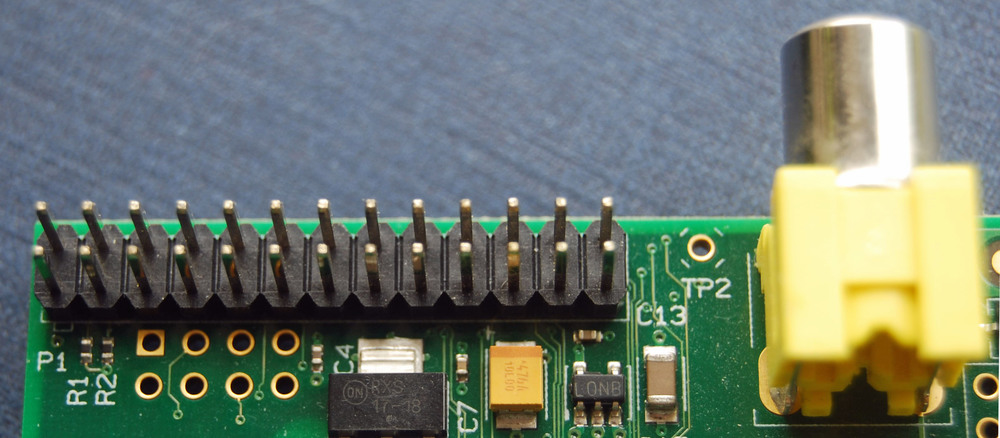
Source: Raspberry Pi
Think of them as the way you connect to the outside world from the Pi. This enables you to write programs that do not run on a computer screen. Each pin acts like a switch that you turn on or off. You can receive input from the physical world, or send output. Basic boards come with 26 pins, and 9 of those pins are power or ground pins. The ground pins are at the end of each circuit that the current has to flow through. The more recent Raspberry Pi boards come with an extra set of 14 pins.
If you are interested in more details on the GPIO pins, this online diagram gives you all you need to understand what each pin is for. There are a myriad number of pins for input / output and ground. These pins are the foundation of physical computing. Depending on your goal, you can use as many as you need.
Mock the fs!
I know what you are thinking, what the heck is fs and why do I care? In Unix-like operating systems, a device file is a driver that looks like a file. In laymenʼs terms, a device driver is a file! Guess what? GPIO APIs are wrappers that read or write to a device file. The file system APIs are concepts that may already be familiar to you. If you have never worked with files in Node.js, I recommend going over the fs module and file systems in Node.js. fs is shorthand for “file system” and enables you to read or write to a plain old file. There is nothing fancy here, all we do is writeFile(), for example, and let GPIO handle the rest. The trick is to know what to write on which file.
There is a handy little npm package called mock-fs that will help us with unit tests. With this library, one can dream up any file on the file system and mock it in memory. What is so radical is we are only dealing with files, thatʼs all we need to do. In a Unix-like system, GPIO behaves like any other plain old file. This gives us freedom on how we can approach this solution.
The crux of the mock-fs library is the mock({}) function. It takes in a single parameter which is a JavaScript object. Inside this parameter, one can dream up whatever file you want. The beauty here is that this all runs in memory, so you can go crazy with unit tests. The interpreter runs in a single process, this means one can override the fs module at runtime. JavaScript is a dynamic language, so we are free to mock any module available to the current process.
The GPIO interface makes a lot more sense once you write good unit tests on it. What I love is that you can get automated test coverage and a nice clean solution. Unit tests improve code readability because it clearly shows you what the API is for.
So letʼs get our hands dirty.
Unit Test All Things
So letʼs open a pin with “out” and test this:
it('opens a pin with out', function (done) {
  mock({
    '/sys/class/gpio/gpio23/direction': ''
  });

  gpio.open(16, 'out', function () {
    const direction = fs.readFileSync('/sys/class/gpio/gpio23/direction').toString();

    should(direction).equal('out');

    done();
  });
});
This testʼs implementation should map physical pin 16 to BCM pin 23 in GPIO. BCM numbers are the Broadcom pin numbers the kernel will see in the device driver. The GPIO Device Driver gives you an overview of where the device files are. As shown, to open up a pin you write the string “out” to /direction. This tells GPIO that we expect to write to this pin. Once complete, check that the file has what it needs. mock comes from the mock-fs library, and fs is the standard file system in Node.js. The kernel says where the path is — version 3.18.x and above is at /sys/class/gpio.
To write to a pin on the board and test this, one can do:
it('writes to a pin with a high value', function (done) {
    mock({
      '/sys/class/gpio/gpio23/value': '0'
    });

    gpio.write(16, 5, function () {
      const value = fs.readFileSync('/sys/class/gpio/gpio23/value').toString();

      should(value).equal('1');

      done();
    });
  });
There are similarities between gpio.open() and gpio.write(). With a write, this writes to a /value file. For a sanity check, I wrote a super high value of 5, but we expect only a 1 on the test. GPIO only takes in a high or low value, just like binary.
I took implementation details from pi-gpio. This library gives you a nice overview of where each pin goes. You can also look up device files on the kernel. Either way, my goal is for you to have a good grasp of the fundamentals, so you can get a clear picture.
Letʼs get a little crazy, how about hitting a breakpoint inside my unit test? I use WebStorm to do this, again, use whatever feels comfortable to you:
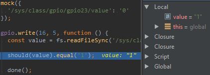
With sound programming, the point is to shorten the feedback loop it takes to find bugs. Unit tests are a nice way to tighten the loop and get immediate feedback.
For simplicityʼs sake, I am writing to a single pin. The rest of GPIO gets summed up in the same way. Open up a pin and tell it what you want to do with it. Read or write to a pin, whatever you need to do. The low-level APIs are device files, so you get to choose how to program each pin.
A Blink Demo
To flesh out each unit test, letʼs look at some common variables:
var sysFsPath = '/sys/class/gpio/gpio';
var pinMapping = {
  '16': 23
};
Above, I’ve defined the pin mapping in GPIO and the path to the device driver. The code below looks at the code that opens and writes to a pin:
function open(pinNumber, direction, callback) {
  const path = sysFsPath + pinMapping[pinNumber] + '/direction';

  fs.writeFile(path, direction, (callback || noOp));
}

function write(pinNumber, value, callback) {
  const path = sysFsPath + pinMapping[pinNumber] + '/value';
  value = !!value ? '1' : '0';

  fs.writeFile(path, value, 'utf8', callback);
}

function noOp() {}
As shown, all one does is writeFile() to a device file. The noOp is a dummy callback in case there is no callback. With this implementation detail, I get passing tests and reassurance that this will work. The value on the write makes sure that it will be set to high or low ('0' or '1').
Onto the finale, a working blinker demo using the APIs shown above:
gpio.open(16, 'out', function () {
  var on = 0;

  var blinker = setInterval(function () {
    gpio.write(16, on, function () {
      on = (on + 1) % 2;

      console.log('ON = ' + on);
    });
  }, 1000);

  setTimeout(function () {
    clearInterval(blinker);
  }, 12000);
});
The setInterval() gets called every second, in the callback I tell it to toggle the pin with a modulus. The blinker has the interval, setTimeout() uses this to clear it after 12 seconds. The callback in setTimeOut() finishes the job and ends the program.
To run the sample code, type:
sudo npm start(You need admin rights to access GPIO on the Raspberry Pi)
I hope GPIO looks more intuitive from this demo. It expects an open pin with a direction. Then, you write to a pin and let GPIO handle the rest of the minutiae.
Conclusion
A test driven approach is perfect for the IoT. In the IoT, your imagination is the limit. A Raspberry Pi could be deployed anywhere in the world — with physical computing, you do not want to ship hardware half-way across the world to debug code. With a test driven approach, there is immediate feedback and reassurance of working solutions. You are more productive and can tighten the feedback loop.
What I love about GPIO APIs is that it is possible to reduce it to a wrapper around the fs module. This gives you complete freedom in writing clean and testable code.
The rest of the sample demo is up on GitHub.